Precision Time Protocol (PTP)
PTP (Precision Time Protocol) is a protocol used to synchronize clocks throughout a packet-based network. It is used to provide a highly accurate and reliable time across local or wide area networks for various systems and applications. PTP is defined in the IEEE 1588 standard.
Quick Links
1. Synchronization principle – PTP
1.2 Syntonization – Adjust the slaves frequency to the master
1.3 Synchronization – Adjust the slaves frequency to the master
1.4 Synchronization of a PTP client
2. Configuration possibilities
2.1 Delay Measurement Mode – End to End (E2E)
2.2 Delay Measurement Mode – Peer to Peer (P2P)
2.3 Multicast and Unicast configuration
2.4 Layer 2 and Layer 3
2.5 1-Step and 2-Step configuration
2.6 Message intervals and timeouts
3. Profiles
4. FAQs about PTP
1. Synchronization principle – PTP
To adapt its time to the master’s time, the slave needs to correct to values. First the slave corrects its clock drift (Syntonization) and then adapts his time by determining the offset based on the duration of the transmission (Synchronization)
1.2 Syntonization – Adjust the slaves frequency to the master
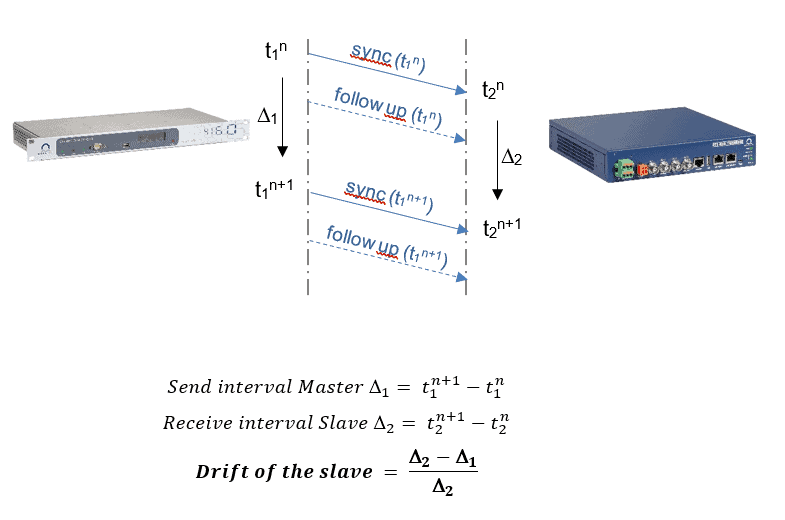
Prior to the time synchronization, the slave uses the consecutive sync messages to syntonize itself to the master (align its frequency). The difference between two consecutive timestamps t1 is telling the slave the interval of sync messages from the master. With his own timestamps t2 he is now able to calculate and compensate his clock deviation. This procedure is repeated regularly to compensate frequency varies over time due to environmental conditions or other changes.
1.3 Synchronization – Adjust the slaves frequency to the master
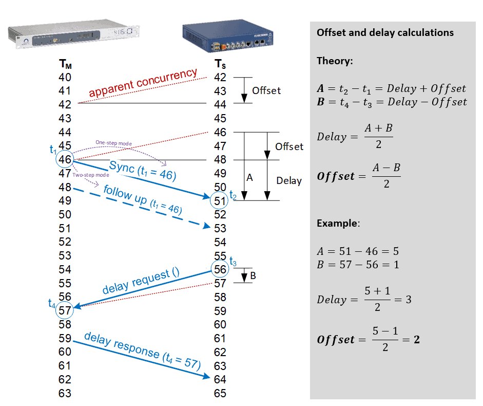
To synchronize the time of a PTP slave the here shown process is used. The master starts it by sending a sync message (and follow up in two-step mode). Then the slave sends the delay request and gets the delay response back. With these messages, the slave collects the four timestamps t1 to t4, which enable him to calculate his offset and adapt his time to the one of the master. The key to the accuracy of PTP is the precision of those four timestamps, because of that hardware timestamping is required.
1.4 Synchronization of a PTP client
The standard does not define how the slave is correcting his internal clock. There are two options:
1. Smooth transition: The slave accelerates or slows down its clock until it is aligned with the master time
2. Immediate step: The slave sets the time to the master’s time (jump forwards or backwards).
It depends on the application, which behavior is used. If it is not allowed to have time jumps (e.g. for logging reasons), the smooth transition is required. On the other hand, if quick alignment is important, it is better to have a jump and then immediately the correct time.
2. Configuration possibilities
2.1 Delay measurement Mode – End to End (E2E)
This delay mechanism requires the Slave to measure the delay between itself and the Master (thus End-to-End). The Master and Slave send IEEE 1588 messages called DELAY REQUEST and DELAY RESPONSE back and forth between the two, allowing the delay to be measured. Once the delay is known, the Slave can adjust its frequency and time to be synchronized with the Master.
Ideally the delay between the Master and the Slave is constant, for example when using a wire. In a real world network, there are Layer 2 and/or Layer 3 devices in between which make the delay variable. If the network devices in between the master and the slave are working as a transparent clock, they add correction values to certain PTP messages, which assists the Slave in removing this variable delay.
2.2 Peer to Peer (P2P)
This delay mechanism requires each network element to measure the delay between its input port and the device attached on the other end of the wire of this input port (the peer device). As the Master sends its view of time (using SYNC messages) towards Slave(s), each network element along the way receives the SYNC message and adds a correction to the SYNC message. The correction includes the measured wire delay of the input port the SYNC message was received on. For Transparent Clocks, the correction also includes the delay through the bridge. This correction is cumulative as it traverses nodes hop-by-hop. As the SYNC message finally arrives at a Slave, the accumulative correction in the SYNC message will contain the total delay from the Master to the Slave. This eliminates the Slave from having to send messages back and forth with the Master. Peer-to-Peer is a newer IEEE 1588 technology, and not all devices deployed today support Peer-to-Peer.
2.3 Multicast and Unicast configuration
Originally, PTP is defined as multicast. The BMCA uses multicast messages to find the Grandmaster and only with multicast, the slave is able to find the master by itself without user configuration.
Multicast
✅ Self-configuration with BMCA
❌ Some networks block multicast
Unicast
✅ less network traffic
❌ pre configuration of masters needed
2.4 Layer 2 and Layer 3
2.5 1-Step and 2-Step configuration
The key of the accuracy of IEEE 1588 is the ability to time stamp PTP messages as close as possible to entering and leaving the physical interface. High accuracy is only possible if hardware is used to capture the time stamps. There are two types of time stamping modes used, 1-step and 2-step:
1-Step mode:
The time stamp is captured in real time as the message starts transmitting out the physical port and as the message is transmitted the time stamp is added on the fly.
2-Step mode:
The time stamp is captured in real time as the message starts transmitting out the physical port, but the time stamp is not added on the fly to this message. A secondary message is used instead to carry the captured time stamp. Older implementations of IEEE 1588v2 used the 2-step time stamping mode, as the hardware was unable to add the timestamp on the fly. Most modern implementations support the 1-Step time stamping mode.
3-Best Master Clock Algorithm:
In a PTP domain all nodes listen for so called «Announce» message:
An Announce message contains quality and priority information of the Clock which sends it
- When no «Announce» messages was received for a defined interval the nodes become Master and start to send their own «Announce» messages
- If a node receives an «Announce» message which is better by its quality, the node stops to send «Announce» messages and becomes Slave
- If a node receives an «Announce» message which is worse by its quality, the node stays in Master and continues to send «Announce» messages in a defined interval
- When the network has determined the best node in the network, this is the only one sending Announce messages => 1 Master, N Slaves
- This algorithm runs all the time, means if another node becomes better or the current Master gets worse than another node the topology changes
- This algorithm is called Best Master Clock Algorithm (BMCA)
2.6 Message intervals and timeouts
PTP defines three different intervals, which can be configured for the different type of messages (described in chapter 1):
Announce Interval:
The interval for the announce message is configurable from 2-7 to 27 seconds.
With this range the announce message can be sent form 128 times per second to once every 128 seconds.
If not otherwise defined the setting 1 is used, where every 2 seconds announce messages are sent out.
Sync interval
For the sync interval the same range as for the announce message is configurable.
The default setting 0 is used, where every second sync messages are sent out.
Delay Request interval
For the delay request interval the same range as for the announce message is configurable.
The default setting 0 is used, where every second delay request messages are sent out.
3. Profiles
A PTP-profile is a selection of optional features and attribute values. The purpose of a profile is to set restrictions on the possible PTP attributes to simplify the interoperability between different PTP devices in a certain application.
IEEE 1588 has defined two default PTP profiles:
- Default E2E:
End-to-End synchronisation on Layer 3 (see chapter 2.3) - Default P2P:
Peer-to-Peer synchronisation on Layer 2 (see chapter 2.4)
Further profiles are defined by different industries for their specific applications.
Power Industries:
IEEE 61850-9-3(Power Utility Profile), EEE C37.238 (power profile)
Telecom Profile:
Frequency Profile defined in ITU-T G.8265.1, Phase Profile defined in ITU-T G.8275.1 & G.8275.2
Broadcast:
SMPTE ST 2059-2 2015
TSN (Broadcast, Automation):
IEEE 802.1AS
4. FAQs about PTP
The main difference lies in the achievable accuracy of the synchronization. When using software timestamps, as is usually the case in software-only mode, synchronization accuracy for slave devices in the range of 10 to 100 microseconds can be achieved. This precision is achievable with standard network devices such as conventional switches and computers acting as software PTP slaves.


